In this tutorial you will learn:
This tutorial relies on the geometries created in the Introduction to Geometric Modeling tutorial. For convenience the Pipe.flowProject has been attached to this tutorial as well.
Please start FlowModeler and open the Pipe.flowProject. The geometry in the Project consist of a pipe with a 90° bend. The pipe cross section is defined by circle. The center of the circle is defined on a cartesian point. The intention is to define the geometry in a way that the pipe can be varied through a set of 3 parameter as specified in the drawing below.

| Dimension | Description |
| R1 | radius of the pipe cross section |
| L1 | length of the upper straight pipe segement |
| L2 | length of the lower straight pipe segment |
The first task that we should do is to reorder the objects in the Model. This does not directly relate to parameterization but gives the Model a cleaner structure.
Currently the objects are ordered in the following way:

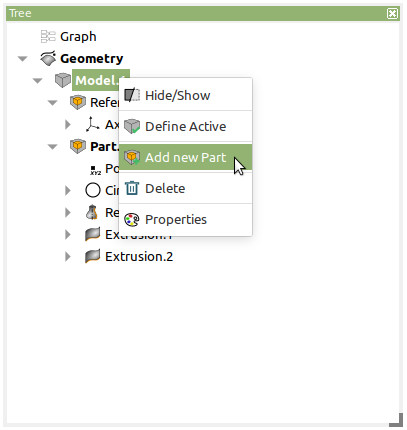
Create two new Parts in Model.1 by doing a Right-Mouse-Button-Click on Model.1 and choose Add new Part from the Context-Menu.
Now rename each Part, except the Part Reference, by doing a Right-Mouse-Button-Click on the Part and choose Properties. Give the Parts following names
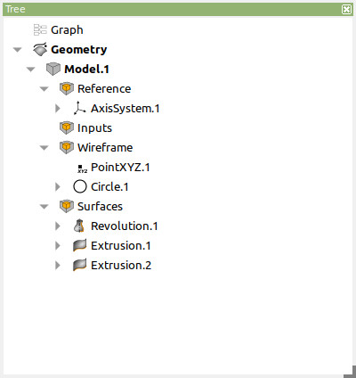
Entities (objects) and Parts can be reordered in the Model by Drag&Drop. Move PointXYZ.1 and Circle.1 to the Wireframe Part and Revolution.1, Extrusion.1 and Extrusion.2 to Surfaces.
Your Tree schould now look like the following image
In FlowModeler values are represented by dimensions of a specific type. A dimension may represent one of the following:
Dimensions are created by FlowModeler automatically with each new Object that is added to the Project. For example the Cartesian Point is created along with three Length-Dimensions representing the X-, Y- and Z-Coordinates. These Dimensions are called Parameter and their value can be changed through the edit dialog of an entity. But these parameter are only visible in the Graph and not in the Tree.
A dimension may also be represented by a Measurement which can be found in the Geometry-Menu. Measurements take some geometric input and are recomputed each time the geometry is updated.
And last but least a dimension may be specified through a Variable which can also be found in the Geometry-Menu.
For the parametrization of the bend we would like to have a set of 3 parameter R1, L1 and L2 for which we can specify a value. As these are supposed to be the main inputs we want them to appear in the Tree. Therefore we will create a Variable for each of them in the Inputs Part.
So if not already active, then please activate the Inputs Part with a Double-Left-Mouse-Button-Click or with Define Active from its context menu. The Inputs part is shown with bold font in the Tree.
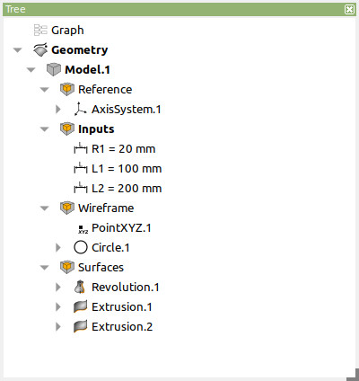
Now choose Variables/Length/Value from the Geometry-Menu and create 3 Variables. Give them appropriate values and rename the Variables to R1, L1 and L2. Your Tree should look like this now:
Next we are going to select the variables as parent dimensions in the geometric objects.
First edit the Circle.1 by Left-Mouse-Button-Double-Click on the rendered curve in the 3D-Viewer or on the item in the Tree.
The Edit-Dialog shows up. Click on the Hand symbol next to the Radius input control. This will switch the control from value-mode to selection-mode. Select the R1-Variable from the Tree. then submit the Dialog with OK.
Next do the same with L1 in Extrusion.1 and L2 in Extrusion.2 for Length.
When the Geometry turns to green color it means that it is outdated and needs to be recomputed. This can be done with the update button. More on that can be found in the Graph tutorial.
In this tutorial you have learned how to connect dimensions to an object. These can be variables, Measurements or existing Parameter. Parent Dimensions can be selected freely as long as they match the expected type in the child entity. The type of the expected dimension in an entity can be found in the usermanual which is linked with each Edit-Dialog.
Downloads