In this tutorial you will create your first Model in FlowModeler. The Model we are building in this tutorial is a pipe with a 90° bend.
In the following we will:
Open FlowModeler and create a new Project either with Create a new empty Project in the Project Navigator or with File/New in the Menubar.
Then the Create Project Dialog will open:
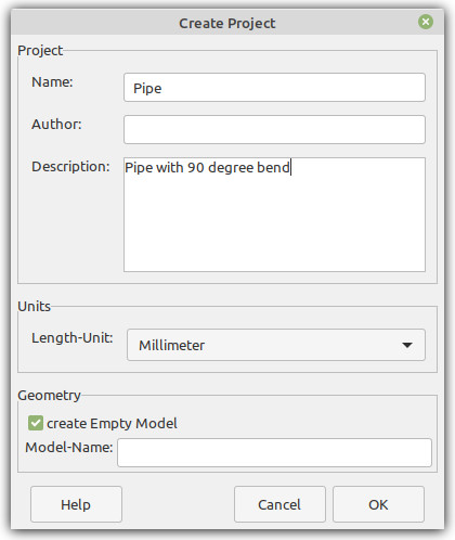
In this Dialog you can specify the Project properties like a Name, the Author of the Project and a short Description. Further the Length-Unit should be specified.
If the create Empty Model checkbox is selected then a new Model will be created in the Project. Also the Model-Name can be specified. If no Model-Name is given, then the Model will be named automatically (e.g. Model.1).
Click OK to create the Project.
Now you will see the Window as shown below:

On the left side of the window you can find the Tree showing the Project structure. Right next to the Tree is the 3D-Viewer that shows all geometries of the current Project.
Expand all the items in the Tree to take a look at the structure of the Project.
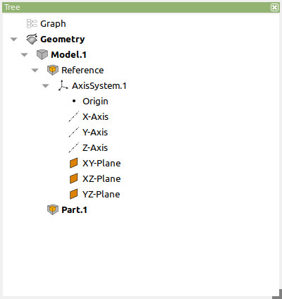
At the top of the Tree you find the Graph and the Geometry items. These items represent the different Modes FlowModeler can operate in when a Project is loaded. We will ignore the Graph Mode for now as it is covered in another tutorial. The Geometry item is shown in bold font as it is the current selected Mode. Modes can be switched by double-click on the item.
The Geometry item contains all the geometric objects of the Project. These are organized in Models and Parts. Models are always attached right below the Geometry item. Parts can be attached to Models or to other Parts.
When operating in Geometry Mode FlowModeler needs to know where new objects should be placed. Therefore Models and Parts can be defined active. The active Model and Part are shown in the Tree with a bold font as well. In the above image Model.1 and Part.1 are the current active Model and active Part respectively. The active Model and active Part can be defined through the context menu shown with a Right-Mouse-Button-Click or by a Double-Left-Mouse-Button-Click on the tree item.
New objects can be added to the current active Part through the Geometry-Menu. The menu is located in the Menubar under Project/Geometry. It will also be shown with a Right-Mouse-Button-Click on the Geometry-Tree-Item or with a Right-Mouse-Button-Click on the background of the 3D-Viewer as shown in the image below.

Now we will create the pipe geometry. The steps to create the pipe are:
To create the center Point choose Points/Coordinates/Cartesian from the Geometry-Menu. This will create a point in the current active Part and show the Edit-Dialog for the point in the lower right corner of the FlowModeler window.

The dialog has the following elements:
Please specify a value of -100 for the X-coordinate and submit the dialog with OK.
To create the circle choose Curves/Circle/Center-Direction-Radius from the Geometry Menu and again an edit diealog will show up. 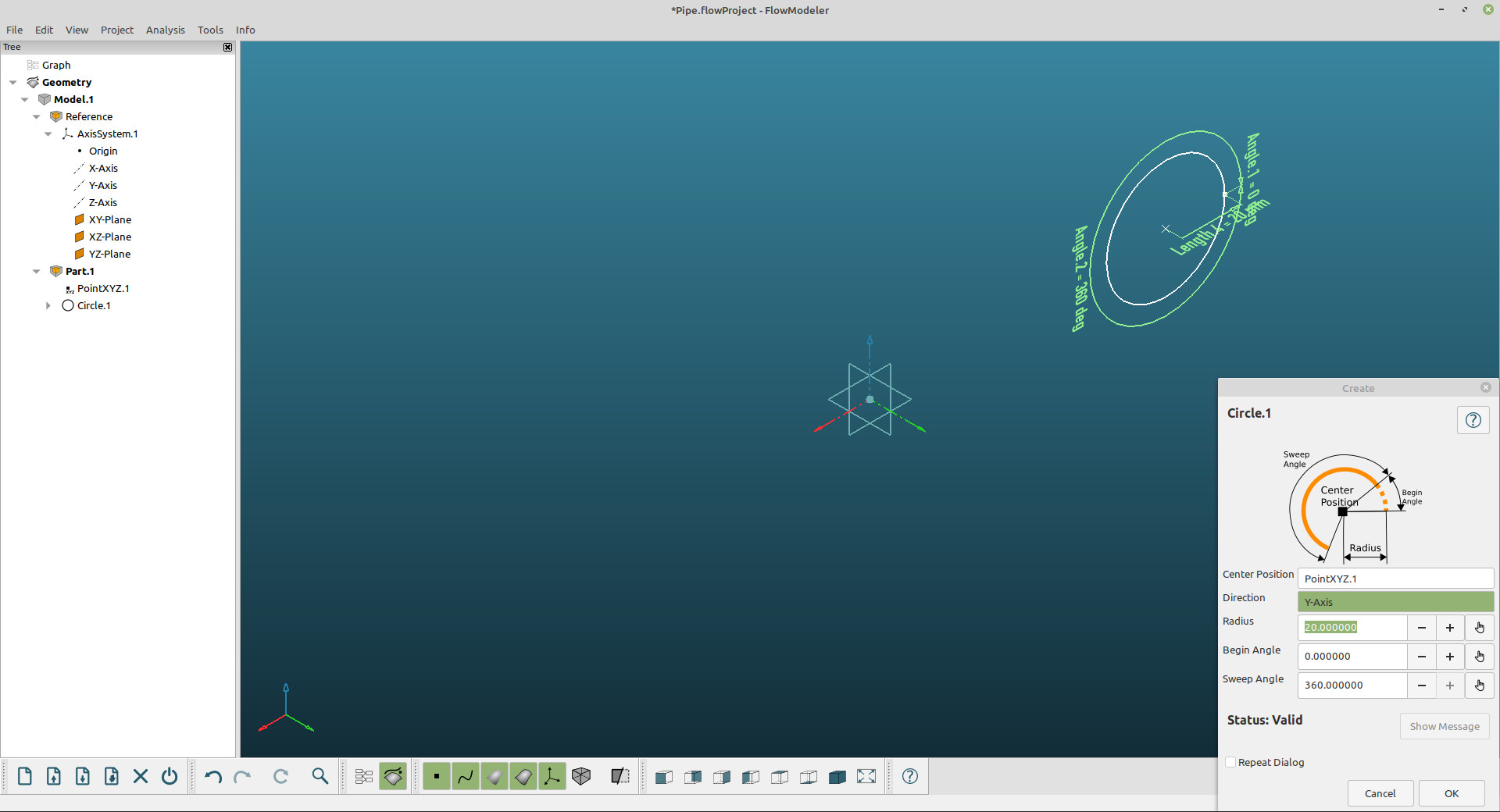
Select the previously created point as Center Position and the Y-Axis as Direction of the circle. Submit the Dialog with OK.
For the bend choose Surfaces/Revolution/Curve-Axis-Angle from the Geometry-Menu.
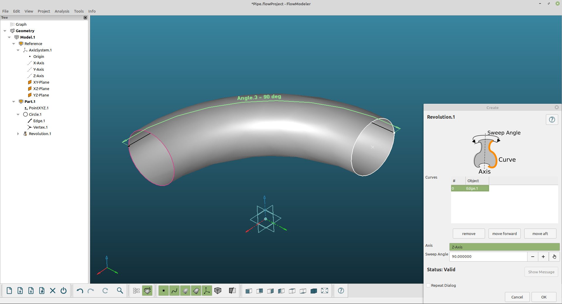
Select the Edge of the Circle under Curves and the Z-Axis as Axis for the revolution. Set the value of the Sweep-Angle to 90 degrees.
The straight pipes can be simply extruded from the open edges of the bend-surface. To create an extrusion choose Surface/Extrusion/Curve-Direction-Length from the geometry Menu.

Select one of the open Edges of the bend as Curves and either the X-Axis or the Y-Axis as Direction. Choose an appropriate value for the Length. Note that in the image above the Repeat Dialog checkbox is activated. That way the second straight pipe can be defined right after the first straight pipe has been created without having to choose it from the Geometry-Menu again. Uncheck the Repeat Dialog box during the definition of the second straight pipe.
You can save the Project with File/Save from the Menubar or the Save-Button in the File-Toolbar.
In this tutorial the basic steps have been shown to create new geometry in a Project. Please refer to the Usermanual on more information about the underlying geometric representation of objects.
Downloads